ANSWER TO RIGGING QUIZ 28
QUESTION:
1. Find a timely and permanent solution for safely lifting the tube bundle high enough to clear the top of the Converter:
There are probably other solutions that would have been satisfactory, but the ones considered are:
a. The single hook in the load block could be replaced by a swivel shackle. This would reduce the rigging height by approximately 1.0’. It would take one week to purchase, air freight it to the site and install it. By its self, this would not be a complete solution, as at least 3’ is needed.
b. Cut approximately 5’ off the top of the Converter. This solution would have worked to set the present tube bundle but not for future replacements. It would also have been very expensive, as the Converter would have had to be stress relieved and hydro-tested after welding the top piece back on.
c. The structural department for the EPC Contractor estimated that it would take at least two weeks to design a five foot extension for the lifting structure, have it fabricated locally, modify the connections at the top of the existing structure and install the extension. A good solution, but not a timely one.
d. The EPC Rigging Engineer also considered moving the diverter sheave side ways so that it was in line with the right hand sheave in the load block. This would provide a maximum fleet distance of 0.15’ for a minimum two-block distance of 3.0’. A layout showed that the load block could only be pulled to within 7.0’ of the stationary block before it interfered with the becket on the dead end. The down side to this option was physically moving the diverter sheave. It entailed removing the diverter sheave from the special frame that housed it and the stationary block. It also meant relocating the diverter sheaves and their supports mounted in the lifting structure. The field estimated approximately three to four days to complete the work.
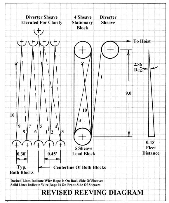
e. After studying the 10 part reeving diagram provided by the fabricator, the EPC Rigging Engineer decided that it could be revised to reduce the two-block distance without moving the diverter sheave.
Note that the original reeving diagram is actually a lacing diagram as the hoist line enters the sheave on the right side of the load block (as you are facing it) and then wraps (or laces) around each succeeding sheave on its way to the left side of the load block. A true reeving diagram is one where the hoist line runs from sheave to sheave in such a manner that the smallest fleet distance possible is obtained, and usually includes a 180 degree reverse bend of the hoist line to keep the hoist line from interfering with its self. See part 3 of the hoist line below that shows a 180-degree reverse bend.
See the revised reeving diagram below that reduced the minimum two-block distance from 12.0’ to 9.0’. It was calculated as follows using a 0.45’ fleet distance:
0.45’/Tan (2.86 degrees) = 9.0’
The Rigging Engineer also decided by inspection that due to the method of reeving, the load block would not hang square under the stationary block but would move somewhat to the left as viewed from the front. By assuming that the load block would move 0.1’ to the left, the side shift from all parts of the hoist line would balanced out. This assumption would provide even more two block distance. See the table below for the results:
PART Resulting fleet distances on the load block
No. (Fleet distance left is negative and right is positive)
BEFORE THE SHIFT AFTER THE SHIFT
Ft. Ft.
1. -0.30 -0.20 (0.30 – 0.10 typ.)
2. +0.15 +0.25
3. -0.15 -0.05
4. -0.45 Worst Case -0.35 Worst Case
5. +0.15 +0.25
6. -0.15 -0.25
7. +0.15 +0.25
8. -0.15 -0.25
9. +0.15 +0.25
10. 0.0 ____________+0.10
Balance -0.60 0.0
The resulting two-block distance was then equal to:
0.35’/Tan (2.86 degrees) = 7.0’
A total two-block reduction of 12.0’ – 7.0’ = 5.0’
The EPC Rigging Engineer then double-checked to make sure that the load block could physically be raised to within 7.0’ of the stationary block and not interfere with the becket on the dead-end.
Solution “e” was then chosen as the solution to the field problem.
SUMMARY:
This quiz is based on an actual rigging event. The fabricator approved the revised reeving diagram and it was transmitted to the field. Upon receiving the revised reeving diagram, the field used the tail crane to hoist the lifting beam off the lifting structure and set it down on cribbing on the ground. The blocks were then reeved per the revised reeving diagram. The lifting beam was then set back up in place on the lifting structure and the load block was hooked to the tube bundle. After hooking up the tail crane, the tube bundle was then hoisted until it cleared the top of the Converter with room to spare and lowered down inside the Converter.
Another way to change the reeving would have been to pull the load block up close to the stationary block and lash it to the lifting beam. Temporary scaffolding supported by the lifting structure could then have been placed under the load block and the reeving of the hoist line could then have been changed in place.
It was later determined that this problem occurred because the overall length of the tube bundle was wrong on the fabricator’s original drawing and the EPC Rigging Engineer was not included in the “squad check” of the revised drawing, which showed a longer length. It can be seen from this “lesson learned” how important it is to include all applicable engineering disciplines in the “squad checks”.
This was a pretty easy fix, but could have been very costly.
End of answer
Maximum Reach Enterprises