ANSWER TO RIGGING QUIZ 26
QUESTION:
1. LUG DESIGN: In designing a lug, the first step is deciding what shackle you are going to use, as the diameter of the pin and bail are important in the lug design/rigging hookup. The maximum sling tension of 366.18 kips occurs in the right sling above the spreader bar. A Crosby G2140 x 200 shackle was chosen because its SWL is 200 metric tons (Te) or 440.92 kips, which is greater than 366.18 kips.
When the Crosby G2140 x 200 shackle was used in the Pad Eye Lug Program found on this website, it resulted in the following lug design. This is not the only lug design that would work for this lift, but it is felt that it is the safest and most economical. This same lug design will be used for all four lugs:
a. 5.00” lug pin hole diameter (0.25” greater than the shackle pin diameter)
b. 8.00” lug radius (Maximum effective lug radius = 7.83”)
c. 3.50” lug plate thickness
d. 16.00” lug plate width
e. 1.25” pad thickness
f. 7.50” pad radius
g. 366.18 kips force on the lug (Worst case force)
h. 90.00 degree angle (Parallel to the centerline of the lug plate)
i. 0.54 (Combined stress factor for the lug plate)
j. 0.30” fillet weld (Between the pads and the lug plate)
k. 1.39” fillet weld (Between the lug plate and the pipe if a
pad eye type lug will be used)
2. LUG DRAWING: See the lug drawing below for details.
With the lug design complete, the next step is deciding how the lug plates will be connected to the spreader bar.
One way would be to use four pad eye type lugs and butt weld the lug plates to the pipe with 1.39” fillet welds. As the 0.38” wall pipe is to thin for this size of fillet weld, this method would require using a 36” long heavy wall pipe section at each end of the spreader bar that was at least 1.39” thick or using doubler pads under the lug plates. Another consideration is that butt welds require strict QC to insure their structural integrity. Also, the pipe sections at the lugs would have to be checked for over stressing or deformation. The lugs would tend to make the pipe sections take on an oval shape. It might be necessary to weld a stiffener plate inside the pipe between each set of pad eye lugs or weld a stiffener ring around the outside of the pipe at each set of lugs. The stiffener ring could be welded to the pipe and the outboard edge of the pay eye lugs. Considering the above, this is not the best way to go.
The recommended way would be to fabricate one curved lug plate for each end of the spreader bar. See the lug drawing below for details of this type of lug plate with identical lugs at each end. The spreader bar would have to be slotted top and bottom at each end with a saw so that the lug plates could slide right in to place with a very close fit. They would then be welded in place with a 0.38” fillet weld. The strips from the slots would then be welded back into place.
The capacity of the 0.38” welds on each lug plate equals 4 welds * 16 in. x 14.85 kips/in * 0.38 = 361.15 kips. This is greater than the horizontal compressive force induced by the inclined slings of 123.10 kips * 1.8 I.F. = 221.58 kips. Very little weld would be required to keep the lug plates stable relative to the spreader bar in the vertical direction. The 0.38” welds would provide much more than enough capacity in both directions.
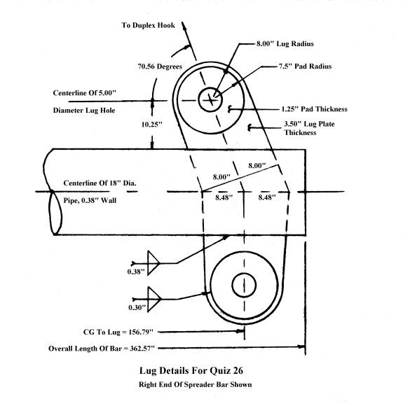
The lug drawing shows the details and final shape of the lug plates.
Note that the top part of the lug plate is 16.00” wide down to where it first intersects the centerline of the pipe. In order to maintain this minimum width, the lug plate at the centerline of the pipe is 2 * 8.48” = 16.96” wide.
The lug plate for the left end of the spreader bar is identical to the one shown above except that the angle is 68 degrees and the lug plate width at the centerline of the pipe is 2 * 8.63” = 17.26” wide.
3. SHACKLE SIZE: The shackle size selected is a Crosby G2140 x 200.
Six shackles would be required for connecting the slings to the four lugs on the spreader bar and the two lifting lugs on the vessel. As stated above, the capacity of these shackles is 200 Te.
4. SLING SIZE: The size selected is a 3.5” diameter, EIPS sling.
In selecting a sling for the right side above the spreader bar, the program for determining the SWL of a sling bent around pins, etc was used. It was found that for a hook diameter of 8”and a shackle bail diameter of 4.5”, that a 3.5” diameter EIPS sling in a three-part configuration would provide a SWL of 372.32 kips with 6.14 kips reserve capacity. All four slings would require the 3.5” diameter sling in a three-part hook up.
Each sling above the spreader bar would be hooked up as follows: One eye would be placed over the hook. The body of the sling would then run down around the bail on the shackle, back up and over the hook and then back down where the other eye would be placed over the bail of the shackle. Each sling below the spreader bar would be rigged the same way except there would be a shackle at both ends.
5. SLING LENGTHS: All four slings are in a three part configuration.
Top right sling length: 101’ – 8.52”
Top left sling length: 103’ – 5.76”
Both bottom vertical slings: 33’ – 2.97”
These lengths were calculated using the following information:
a. The distance from the center of the 200 Te shackle pin to bearing on the bail = 18.07”
b. The sling length in contact with the 4.5” dia. bail of the shackle = 12.57”
c. The sling length in contact with the 8.0” dia. hook = 18.06”
For example, the length of the top right sling was calculated by the following formula: 3 * (414.70” – 18.07”) + 12.57” +18.06” = 1220.52” = 101’ – 8.52”
Where 414.70” is the distance from bearing on the hook to the centerline of the top right lug and the 3 is for three parts of sling.
In order to maintain the vertical distance from bearing on the duplex hooks down to the centerline of the top lugs on the spreader bar of 391.06”, and from the centerline of the spreader bar down to the centerline of the lifting lugs on the vessel of 180”, slings should be used that have been measured for length under a SWL during load testing. Most sling manufacturers are able to fabricate matched slings so their length, measured under a SWL, is within 1.0” of each other and within +/- 6.0” of the length specified on the purchase order. Therefore each pair of slings should be purchased with the specification that their lengths should be within the plus 6.0” tolerance or all slings should be within the minus 6.0” tolerance, not one 6.0” minus and the other 6.0” plus. If both the top slings ended up being 6.0” longer than the specified length on the P.O., then the net increase in the vertical distance 391.06” would be about 2.0” and the effect on the strength of the spreader bar would be less than 0.01%.
SUMMARY:
Even though this was a quiz, the information from it can be used to make a spreader bar drawing and a rigging hook up drawing. They can then be used to make an actual 650 kip lift.
Maximum Reach Enterprises