HELP FILE FOR: DESIGN PROGRAM FOR ADJUSTABLE PIPE SPREADER BARS WITH END CAPS:
DEFINITION:
This program can be used to design pipe spreader bars fabricated from 4”, 6”, 8” and 10” diameter pipe. These spreader bars have one end cap on each end that fits over a pipe insert. The program is applicable for:
1. Traditional pipe spreader bars that do not have support lugs welded to the end caps. Clamp plates are provided for these spreader bars to keep the spreader bars from slipping down the vertical portion of the slings during lifting. See the spreader bar sketch below.
It is recommended that when every possible that the bottom of the curved end plate on each end cap be located just above the swage fitting on the bottom eye of the sling. This will prevent any downward slippage of the spreader bar.
When designing a traditional spreader bar, omit all references in the program and in this help file to support lugs.
For end cap fabrication, select a pipe size from the traditional spreader bar list.
2. Pipe spreader bars that have support lugs welded to the top of each end cap to keep the spreader bars from slipping down the vertical portion of the slings during lifting. See the spreader bar sketch below.

The spreader bars are adjustable for length, for pipe schedule and for lift sling angles. The program is also applicable for spreader bars where the CG of the load does not hang under the center of the bar. In this case, the CG will be located on a point on the bar that is defined by a vertical plumb line that runs down from the hook thru the CG of the load. Again, this is not necessarily the center of the bar.
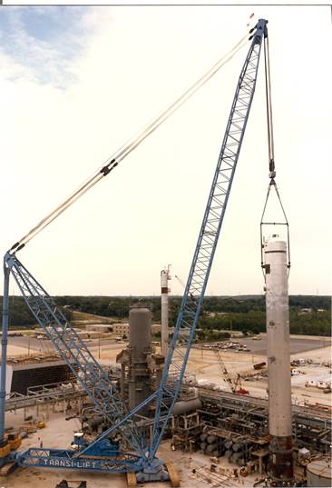
The photo below shows a 450-ton vertical vessel being lifted by a 10” diameter x 16’ long XXS pipe spreader bar with a doubled 4.5” diameter x 90’ EIPS sling over each curved end plate. The slings were at 70 degrees with the horizontal. As the CG was centered on the spreader bar, its lifting capacity was actually 490 tons. Note that support slings were not used for this lift to hold the spreader bar in place
PROGRAM OBJECTIVE:
The objective of this program is to help the spreader bar designer develop a design that is efficient, economical and safe. It can also be used to check the design of an existing spreader bar. The output information conforms to the requirements of AISC and ASME B30.20. The program also provides the tensions in the lifting slings, the tensions in the support slings and their lengths, i.e., the rigging hook up. Refer to the comments and examples at the end of this help file for design tips.
WHAT THE PROGRAM DOES NOT DO:
1. The program asks for the number of parts of lift sling(s) that will be used on each end of the spreader bar and multiplies this number by the SWL in a straight pull to get the total lift sling capacity. It does not take into account any bending losses due to the bight of the sling bending over the hook for a doubled sling, the bight of a sling over the bail of a shackle, the slings bending around the end caps of the spreader bar, etc. The program user must compare the actual tensions in the lift slings above the spreader bar with the total lift sling capacity value listed. If there is bending that needs to be accounted for that will lower the total lift sling capacity below the actual lift sling tensions, then the user needs to select a lift sling with a larger capacity to account of this loss. The program “Safe Working Load Of A Sling” located in this design section can be used to solve for the actual SWL of slings. Make sure that this value is greater than the actual tensions in the slings above the spreader bar.
LOOK UP TABLE
FOR SLINGS:
The sling look up table contains information on three types of slings, ie, Improved Plow Steel (IPS), Extra Improved Plow Steel (EIPS) and Extra Extra Improved Plow Steel (EEIPS). The sling diameters listed with each type of sling are the most commonly used and available. The SWL of each sling includes the efficiency loss due to the swage fittings. The user can select a sling type/diameter and the SWL will be imported into the appropriate input field in the program.
LOOK UP TABLE FOR 4”, 6”, 8” & 10” DIAMETER
PIPE:
The properties for Standard wall (STD), Extra Strong wall (XS) and Extra Extra Strong wall (XXS) pipe are included in the lookup table in the program. The user can select a pipe diameter with a certain wall thickness and the properties will be imported into the appropriate input fields of the program.
NOTE:
Only a 10” diameter XXS (Sch. 140) pipe size is shown in the look up table because the inside diameter of a Sch. 160 pipe is to small to fit over a 8” diameter XXS pipe sleeve and Sch.120 pipe and smaller leaves to much play.
FABRICATION DRAWINGS:
By clicking on the “DRAWINGS” button, the program user can view:
1. Three drawings for traditional end caps without support lugs that are approved for fabrication. These drawings provide all of the details needed for fabrication of 4”, 6” and 8” end caps.
2. Three drawings for end caps with support lugs that are approved for fabrication. These drawings provide all of the details needed for fabrication of 4”, 6” and 8” end caps. The drawings include the details for the support lugs.
3. One drawing showing how to use a 10” XXS (Sch. 140) pipe insert with 8” spreader bar end caps, utilizing a 8” XXS pipe sleeve.
4. One plate spacer drawing that shows details for fabrication. This drawing is to be used in conjunction with end caps that have support lugs.
NOTES:
It should be noted in the drawing for a 4” diameter end cap, that the actual pipe size is a 6” diameter double extra strong pipe that will fit over any 4” diameter pipe insert. Therefore, it is called a 4” diameter end cap because it is used with 4” diameter pipe inserts. The same holds true for the 6” and 8” diameter end caps.
Acad or pdf drawings are available and will be sent via email upon request.
MAKING A LIFT:
Making a lift using this type of spreader bar entails the following procedure:
1. Run the program and determine the following:
a. Lift slings with sufficient capacity for the lift
b. Support slings with sufficient capacity for keeping the bar in place.
c A pipe diameter and schedule with sufficient capacity for the lift, either a 4”, 6”, 8” or 10” and either a Std, XS or XXS wall
2. Select the corresponding fabrication drawing and have the end caps fabricated from that drawing.
3. Fabricate an assortment of plate spacers to be used to keep the lift slings centered on the end caps with support lugs.
4. Based on the total length of the spreader bar, determine the pipe insert length and have it fabricated. See the example below for determining the pipe insert length.
5. Assemble the end caps, the pipe insert, the plate spacers and slings per the rigging hook up drawing.
6. Hook the rigging up to the lift crane.
7. Hook the rigging up to the load.
8. Make the lift.
It’s that easy!
COMMENTS:
1. After using this type of spreader bar for many years, it is my opinion that it is easier to design, fabricate and safer to use than most other spreader bars. It is also very economical in cost as the slings are in tension and the pipe is in compression with very little bending. An 8”diameter x 10’ long XXS pipe spreader bar can handle loads up to 300 tons with the lift slings at 60 degrees with the horizontal.
2. For a project that has relative
light plant equipment to be installed, it is recommended that at least four 4”
diameter end caps and two 6” diameter end caps be fabricated or purchased. This would give the field the option to lift
the vertical vessels using one of the three spreader bars and to lift
horizontal equipment modules using two 4” transverse spreader bars plus one 6”
longitudinal spreader bar. For a project
that has heavier items to set, then at least four 6” end caps and two 8” end
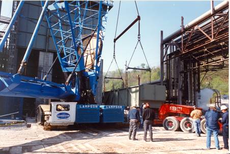
caps need to be fabricated or purchased for the same reasons as above. See the photo showing two 6” transverse
spreader bars and one 8” longitudinal spreader bar lifting a 150-ton heater
section. Note that support slings were
not used for this lift to hold the spreader bars in place.
3. Another advantage of using this type of spreader bar is that one long sling is used on each end of the bar. Moving the bar up or down sets the angle of the inclined section of the sling above the spreader bar. Clamping the slings for end caps without support lugs accomplishes this. Shortening or lengthening the support slings accomplishes this on spreader bars with support lugs. Most spreader bars require two inclined slings above the spreader bar and two vertical slings below the spreader bar, all sized for a certain length.
4. The bolts that connect the pipe inserts to the end caps are there to just hold the spreader bar together until it is hanging in the air on the hook. The bolts do not carry any shear load during lifting. As the holes in the heavy wall end caps are 1.25”, the holes in the pipe inserts are 1.5” and the bolts are 1”, there is plenty of play so that the bolts are not in shear. The pipe inserts bear up against the round disks welded inside the end caps, which means the round disks take the entire compression load. The welds have been designed for the maximum allowable horizontal load in the pipes.
5. It is recommended that the sling angles with the horizontal should always be 60 degrees or higher. Having said that, the end caps are designed so that sling angles down to 45 degrees can be used, as there are some cases where the lift requirements dictate sling angles less than 60 degrees.
6. The U-Bolt guides that bolt to the top of the curved end plates were originally used to keep the lift slings from being bent and damaged during assembly, ie, when up righting the spreader bars from the horizontal where they were laying on their sides to a vertical position where they were hanging under the hook. They also helped to keep the lift slings some what centered on the end caps. Even though using the support lugs and plate spacers will keep the slings centered on the end caps, the use of the guides is still recommended as an added precaution.
7. Rigging codes state that all lift and support slings be proof tested to twice their SWL. It is recommended that they also be measured for length while under their SWL and using standard sized pins in the eyes. The length of the eyes should also be measured at this time. This measurement would be from bearing on the eye of the sling to the far end (inboard end) of the swage fitting. This measurement is usually around 6’ and is required so that the designer of the rigging hookup doesn’t size the lift slings such that the bottom or vertical swage fittings on the sling eye land on the curved end plates. The vertical swage fittings must be located below the curved end plates.
CURVED END PLATES:
1. In fabricating the curved end plates for the end caps, it is important to use the radius shown on the fabrication drawing so that the lift slings will not be damaged due to a sharp bend.
2. The curved plates for the end caps have been designed for using one lift sling separately (one part), one lift sling doubled (two part), two lift slings side by side (two parts), or in some cases a tripled (three part) lift sling.
PIPE INSERTS:
1. Pipe inserts of the same diameter and wall thickness can be welded together to make longer spreader bar lengths. The only requirements are; the two pieces of pipe must be laid out in a jig so that the two sections will be straight and true with each other and full penetrations welds must be used.
2. When selecting a pipe insert, it is usually more economical to select a standard wall pipe than an extra extra strong one. For example, if a certain load requires say a 6” diameter extra extra strong pipe, then check to see if an 8” diameter standard pipe insert would work. If it will work, it will be cheaper to procure, because standard pipe is readily available around most construction sites, where as extra strong and extra extra strong pipe are usually a special order.
3. An advantage of using this type of spreader bar is that the pipe inserts can be cut to length so that the overall length of the spreader bar can be the same as the distance between the lifting lugs. Pipe inserts are usually quite inexpensive, so a pipe insert can be fabricated for each lift if necessary or shared between several lifts if the resulting angle of the vertical slings from the lifting lugs up to the end of the spreader bar is not more than 0.5 degree out of plumb. By weld beading the lengths and wall schedule (thickness) on the inserts, they can be easily identified when they are needed.
4. Refer to the appropriate spreader bar drawing listed to determine the required insert length of pipe for an adjustable spreader bars, or use the following information. For example, the end cap deduct is shown below for the pipe spreader bars:
PIPE SPREADER BAR END
CAP DEDUCT
Diameter For Both Ends
(Inches)
4" 9.5"
6" 12.5"
8" 15.0"
10” 42.0”
EXAMPLE:
The pipe insert length for a 4" diameter x 12' adjustable pipe spreader bar using 1" diameter slings would be: 144" - 2 slings*1" diameter/2 - 9.5" =133.5" = 11'- 1.5"
The 12’ length of the spreader bar would be measured from centerline of vertical sling on one end of the bar to the centerline of the vertical sling on the other end of the bar, ie, center to center of lifting lugs.
END CAPS WITHOUT SUPPORT LUGS:
Calculations show that for sling angles of approximately 60 degrees, the friction force between the slings and the curved end plates on the spreader bars during lifting is approximately equal to the vertical component of the sling force pushing down on the end plates. Therefore, during lifting, the friction force will almost keep the spreader bar from slipping down the slings. To ensure that the spreader bar does not slip, clamp plates with half round bars that act the same way as U-bolts on cable clamps, are bolted to the bottom of the curved end plates. A torque value is not specified for tightening these bolts. It is recommended that they be tightened the same way that cable clamps normally are tightened, so they bite into the cable but not so tight that they damage the cable.
END CAPS WITH SUPPORT LUGS:
I am very comfortable using the spreader bar with only clamp plates to keep the spreader bar from sliding down the vertical portion of the lift slings. However, riggers without experience in using the spreader bars with the clamp plates have expressed concern about the spreader bar sliding down the vertical portion of the lift slings during lifting. In order to alleviate this concern, the end caps have been redesigned so that a support lug is located on the top of each end cap. The program calculates the length of the support slings from bearing on the hook to the center of the support lugholes. It also calculates the tension in the support slings, neglecting the friction resisting force between the lift slings and the curved end plates. If the CG of the load is not in the center of the spreader bar, the tension in each of the support slings is not the same. The program selects the largest tension for the output value.
Crosby G2130 metric shackles have been used in the design of the support lugs. The shackle sizes and the lengths (y) from the center of the shackle pins to bearing on the shackle bails are given below:
Support lugs for: Shackle Size Length (y)
4” diameter end caps 17 Te 6.58”
6” diameter end caps 25 Te 8.02”
8” diameter end caps 35 Te 8.90”
The support lugs have been designed for the SWL of the shackles.
LIFTING WITHOUT SUPPORT SLINGS:
The end caps with support lugs welded to the top of the pipes can still be used without support slings if:
a. The bottom of the curved end plates on the end caps are positioned down against the top of the vertical swaged fitting on the slings
b. The total thickness of the plate spacers used to keep the slings centered on the curved end plates will allow the clamp plates to be tightened such that they are pressing firmly against the lift slings
Note in the photo shown lifting the heater section that the curved end plates on the longitudinal spreader bar are resting on the top of the bottom swage fitting of the lift slings. The curved end plates on the transverse spreader bars are not.
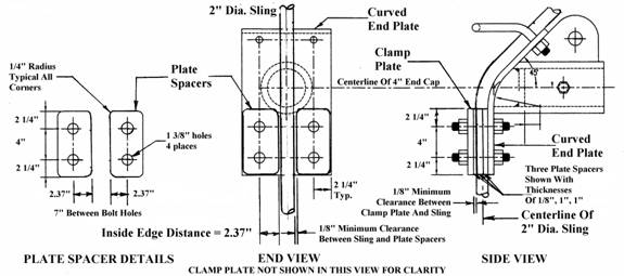
PLATES SPACERS:
An assortment of plate spacers of various thickness and widths need to be fabricated to keep the slings centered on the end caps with support lugs and to prevent the clamp plates from bearing on the slings such that they restrict longitudinal movement. The plate spacers have been sized so that they are interchangeable between all three sizes of end caps.
The shape of these plate spacers must conform to the shape of the outside of the curved end plates, ie, have two holes drilled in them and the same outside edge distances of 2 ¼” from the centerline of the holes. The plate spacers with various inside edge distances measured horizontally from the centerline of the holes are required to make sure that any diameter of sling(s) being used will not have more than 0.5” of side play on the curved end plates.
For example, the horizontal center-to-center distance between clamp plate bolt holes for a 4” dia. spreader bar is 7”. For a 2” sling, the inside edge distance of the plate spacers, measured from the centerline of the bolt holes to the side of each sling would be 2.37”. This will provide between 0.25” and 0.5” of clearance between the sling and the plate spacers, depending on the fabrication tolerances of the curved end plate, the clamp plates and their drilled holes. The total thickness of the plate spacers would have to be at least 2.13” to keep the clamp plate from bearing on the 2” sling. See the sketch below.
CLAMP PLATES FOR SPREADER BARS WITH SUPPORT LUGS:
The purpose of the clamp plates is to hold the lift slings in alignment against the curved end plates and yet leave them free to move. This is accomplished by using plate spacers with the correct inside edge distances to keep the lift slings centered on the curved end plates and the correct thickness so that when the clamp plates are tightened against the plate spacers, the lift slings are free to move longitudinally (up or down the curved end plates) as required to equalize the slings.
The dimensions of the clamp plates are the same for all sizes of end caps.
When a spreader bar is being used to lift a load where the lifting attachments are trunnions or equalizer sheaves, ie, a vertical vessel with trunnions, doubled lift slings are generally used where the eyes of the slings are over the hook and the bights (center of the slings) are around the trunnions. In this case, there will be side loading to the lower clamp plate stud bolts. The user should calculate this side load and if necessary, up grade the clamp stud bolts to A 490 bolts with the threads excluded from the shear area to obtain maximum shear capacity.
TOTAL LOAD:
The total load is the combined weight of the load and any items that might be included for erection, i.e., trays, insulation, piping, platforms & ladders, fire proofing, weight contingency, rigging, etc. It is input as kips (1 kip = 1,000 lbs.).
ANGLE OF THE LEFT SLING:
When the CG of the load does not hang under the center of the spreader bar, different lengths of slings must be used to keep the hook centered over the CG. Use the smaller of the two sling angles for the input value for the left sling. It is recommended that all sling angles be kept at 60 degrees or greater. The program will calculate the angle of the right sling.
HORIZONTAL DISTANCE, BEARING TO BEARING
ON DUPLEX CRANE HOOKS.
This horizontal distance is measured from the center of the bearing area on one prong to the center of the other prong. If a load block with a single hook is being used, enter zero for this value. See the elevation view of the spreader bar and rigging.
LENGTH OF THE SPREADER BAR, overall:
The overall length of the spreader bar is measured from centerline of the vertical lift sling on one end of the spreader bar to the centerline of the vertical lift sling on the other end. This distance is used in figuring the bending in the spreader bar due to its own weight, the bending due to deflection of the pipe and to calculate the pipe insert length.
EFFECTIVE
LENGTH FACTOR (K):
The program uses an effective length factor of 1.0 for spreader bar design.
MODULUS OF ELASTICITY:
The program uses a modulus of elasticity of 29,000 ksi for spreader bar design.
IMPACT FACTOR:
A minimum impact factor of 1.80 should be used for new design in order to conform to ASME B30.20, which limits stresses to .33*Fy. By using 1.80, the allowable stresses can be used as printed in the AISC Manual.
The program allows a variable impact factor to be used so that when checking an existing design, the impact factor can be determined that was used to calculate the stated allowable load for the spreader bar. If the impact factor turns out to be less than 1.8, the program user will then have to make a decision as to the structural integrity of the spreader bar based on the actual impact factor, its application and the risk involved.
Input of the impact factor is limited to 1.25 or greater. If an impact factor less than 1.25 is used, the program shows “error” in all of the output fields and a message is displayed stating that the impact factor is less than 1.25.
The impact factor is included in the output value for the combined stress check. It is not included in any other output values.
KL/R:
The program uses a slenderness ratio (kl/r) equal to a maximum of 120. If this maximum is exceeded, “error” will show in all of the output fields. A message will be displayed that asks the user to increase the member size in order to reduce the kl/r down below 120.
The overall length of the spreader bar is used to calculate kl/r.
ECCENTRICITY:
For a certain sling angle, somewhere around 55 degrees, there is no eccentricity in the design of this type of spreader bar. But, for sling angles below 55 degrees, the eccentricity occurs above the centerline of the bar, causing a bending moment that bows the pipe down in the middle. With sling angles greater than 55 degrees, the eccentricity occurs below the centerline of the bar, causing a bending moment that bows the pipe up in the middle. A negative value for the bending moment indicates that the pipe spreader is being bowed up in the center.
By changing the sling angles to obtain a negative bending moment, the program user can use it to offset the positive bending moments caused by the weight and deflection of the pipe, thereby reducing the net bending moment in the bar. Sling angles at or above 60 degree usually produce the smallest combined stresses in the pipe due to the negative bending moments and the reduced compression load in the pipe.
When the CG is not located in the center of the bar, the eccentricities are different at each end. That is why the combined stress is calculated at each end and neither one can be greater than 1.0.
NET BENDING MOMENT IN THE BAR:
The net bending moment can also be
negative or positive for the same reason as given above.
AXIAL AND BENDING
STRESSES:
The program checks the actual axial stress (fa) against the allowable axial stress (Fa). If fa > Fa, then “error” will show in all of the output fields. A message is displayed, asking the user to reduce this stress. It makes the same check for the bending stress.
COMBINED STRESS CHECK:
The combined stress check is the governing factor concerning the allowable capacity of the spreader bar. This value must always be less than 1.0. If it is greater than 1.0, the program will show “error” in all of the output fields. There are several ways that this value can be lowered. The load can be reduced, the angle of the lift slings can be increased, or a member with a larger cross-section can be chosen. Sometimes a combination of the above must be used.
For a given run, if the combined stress check is slightly greater than 1.0 and the output fields all show ERROR, it is recommended that the input value of the load be reduced until ERROR is no longer displayed in the output fields. The user can then look at the output values and decide if the angle of the slings should be increased, etc. If the sling angle is increased and the combined stress check drops below 1.0, then the input value of the load can be increased until the combined stress check is equal to 1.0.
EXAMPLE 1:
The “sample values” button contains input for a typical spreader bar problem. By clicking on “sample values” the input values are shown with the output values blank. By then clicking on “calculate”, both the input and output values are shown.
EXAMPLE
2:
In example 1, the total length of the support slings is 295.43”. From the next to last paragraph in the Support Lug section above, note that the distance from the center of a 35 Te shackle pin to bearing on the bail is 8.90”. Therefore, a support sling is required that is 295.43” – 8.90” = 286.53” long = 23.88’ long. For this example, two 24’ (288.00”) long support slings are available that have been measured under their SWL.
Use the following procedure to determine the actual lift sling angles if these 24’ support slings are used. Add the 8.90” of shackle “y” distance to the 288.00” to get 296.90” for an overall support sling length. In the program change the left sling angle to 60.15 degrees and note that the length of the support slings is now 296.88”, the lift sling length is 312.42” and there are minimal changes to the other output values, ie, the combined stress check is still 0.99.
If the lift requires that there be at least 8’ of vertical lift sling length from the centerline of the spreader bar down to bearing on the lift shackles, then a 35’ lift sling will provide the 312.42” (26.04’) of lift sling above the centerline of the bar and 107.58” (8.96’) below the bar.
END OF HELP FILE